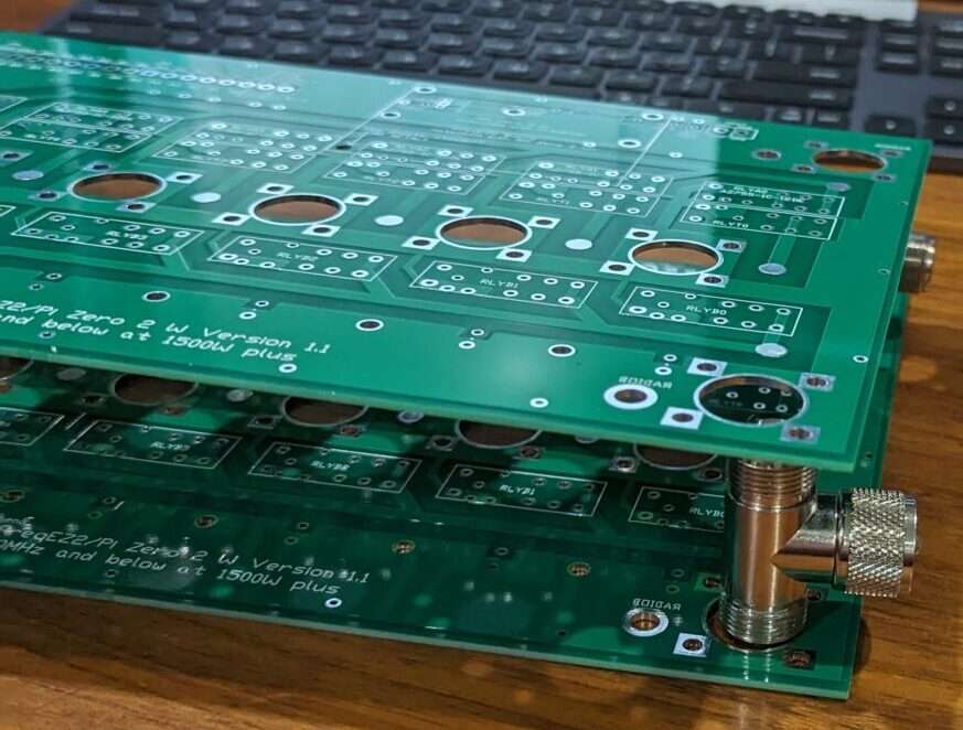
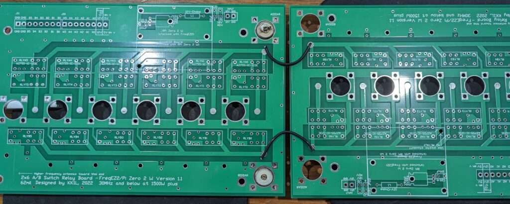
Shipping information
I ship your boards using United States Postal Service (USPS) from Jericho or Essex Jct, Vermont typically using Priority Mail or Priority Mail International using a “Flat Rate Envelope”. Note that the 2×8 boards cannot fit in the flat rate envelopes which is why there is a small upcharge when ordering them. They will ship in a larger bubble envelope.
I typically can get an order out within a few days. Two reasons there may be a delay. In each case I will let you know.
- I could be away from my home travelling. I do my best for you.
- I do not keep a large stock of boards, so I may have to order more to complete your order
The web presence looks pretty good, but I am a simply a hobbyist doing my best to provide a DIY alternative for you.
Why do I need this?
Let’s say you have a tribander, a 40m dipole, and an Inv-V for 80m & 160m? You have an Elecraft K3 for a home radio and an Elecraft KX2 you like to use for POTA. You are getting pretty good at operating a contest with the K3 running and using the 2nd VFO or the sub-receiver for S&P. If you are wishing you could S&P efficiently on a second band or even try your hand as dual CQ, then this setup is what will allow you to share your antenna feeds without any worry about one radio transmitting causing damage to the other. You can purchase a 2×6 relay PCB, build it up from the parts list provided (or your junk box), hook up a pair of rotary switches (one for each radio), and you are ready to go!
The above example is not automatic at all. But since your radio or logging program can output which band each radio is on, you can control the switch through a band decoder to automatically pick the right antenna for each rig! There is nothing particularly new about this at all, but when YOU have it working at YOUR station it is pretty sweet!
You can go to the next level and have the antenna switching be handled through WiFi using K8UT’s FreqEZ, or a home brew method. This is how I switch my antennas. I only feed a pair of coax (one for each radio) and 12V to the base of the tower for full 2×6 selectivity! No long runs of control wires for squirrels or mice to chew…and yes they sometimes like to chew insulation!
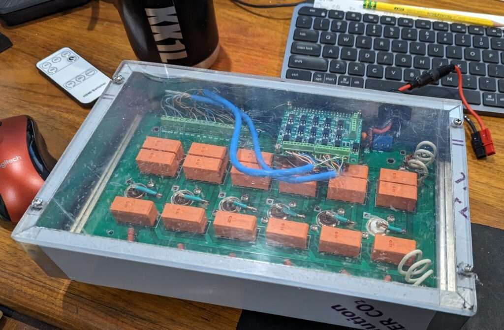
This version has a plexiglass lid to allow the Rasberry Pi Zero to connect to WiFi. This is good for something within easy range of your access point…if your mobile phone can connect to WiFi, so will this setup. Also don’t worry about stray RF. It is not a problem with a well behaved antenna system. The PCB wiring is stripline.
Do you provide fully assembled units?
In a word, no. Surely it would be nice to have that option. It is however a lot of extra work and commitment to provide that service. As I write in my Vision statement my goal is to…
Provide access to the unique PC Boards required for the basis of your DIY antenna switching. There are lots of folks who have the skills to solder their own boards, drill their own chassis’, exercise their brains, get their hands dirty, and save some $$ in the process.
I have put together a variety of both switches and controllers including the prototypes. I am considering designing an assembled and microcontroller based ready dual decoder / controller. Time will tell if I get around to doing that. A fun project for sure, but there are options already out there.
Dual Band Decoder / Controller Parts List
These parts are available in the Mouser Project File link, and are easily available to edit and put into your Mouser shopping cart. I have no affiliation with Mouser, but just that it is super easy and convenient. Get the parts however you would like!
Some stuff from Amazon you could consider for the build https://www.amazon.com/hz/wishlist/ls/XDS80BGQWSBG?ref_=wl_share
Relay Control Section – This is all you need to build if you are going fully manual:
- 3 – CD4011 (sockets optional)
- 2 – Euro Connector (optional, but convenient)
- 12 – PNP Transistor MPSA92 (nearly any PNP will work. Location marked “2N3906”)
- 13 – 100K Ohm 1/4W (not critical…47K to 150K is fine)
- 12 – 5.6K Ohm 1/4W (board is marked 10K)
- 15 – 1K Ohm 1/4W (can change to vary LED brightness)
- 3 – 0.01uF ceramic (not critical!! 0.1uf & 0.001uF are okay too)
- 12 – 27V MOV (near transistors marked “0.01”)
- 2 – 7 Position Rotary Switch
- 1 – 72 pin 100mil SIP Header (optional)
- 1 – Green LED (power)
- 12 – Red LED
- 13 – LED Chassis Clip (drill 11/64”)
Band Decode Sections – These can be used separate from the relay control section if desired:
- 1 – 4N25 1 Ch Opto-isolator
- 2 – PS2501-4 4 Ch Opto-isolator
Note: Can use PS2505-4 which can allow active or active 0 BCD inputs - 2 – CD4028
- 2 – CD4029
- 18 – Switching Diode 1N914 (most any switching diode will do)
- 8 – 3.3K Ohm 1/4W
- 9 – 10K Ohm 1/4W
- 9 – 0.01uF ceramic (not critical!! 0.1uf & 0.001 uF are okay too)
- 2 – DB25 PCB Mount Female
- 2 – Yellow LED (optional for Auto mode)
- 2 – 1K Ohm ¼ W (optional for Auto mode)
- 2 – LED Chassis Clip (drill 11/64”)
AC-DC Converter Section:
- 1 – 12V Regulator
- 4 – Rectifier 1N4001
- 1 – 100uF 50V
- 1 – 1uF 50V
- 1 – SPST Switch
2×6 Assembly Parts List
These parts are available in the Mouser Project File link, and are easily available to edit and put into your Mouser shopping cart. I have no affiliation with Mouser, but just that it is super easy and convenient. Get the parts however you would like!
Some stuff from Amazon you could consider for the build https://www.amazon.com/hz/wishlist/ls/XDS80BGQWSBG?ref_=wl_share
Basic Build Parts:
- 12 – Diodes 1N4001 (relay back EMF suppression)
- 12 – 0.01uF ceramic capacitor (relay noise suppression)
- 6 – 50 Ω 50W Thick Film TO-220-2 (or 51Ω 3W Metal Oxide Resistor)
- 18 – RZH3-1C4-12 Relay or equivalent (Form-C SPDT non-latching 12V 16A 5mm pin pitch)
- 8 – SO-239 Launcher (chassis mount)
- 2 – Euro 10 port Fixed Terminal Block (optional, but convenient)
- 16 – 6-32 x 1” stainless screws (length is generous)
- 32 – 6-32 stainless nuts
- 1 – 2×6: 7”x11”x 2” Hammond Al Chassis and bottom plate
Raspberry Pi Zero / FreqEZ Parts:
- 1 – Raspberry Pi Zero 2 W or Zero W (any RPi works, but small form factor is important for this install)
- 1 – UFL SMD connector (if not already on the R Pi Zero and you will add an external antenna)
- 1 – UFL to SMA chassis mount cable (if you will add an external antenna)
- 1 – FreqEz2 Band Decoder / switch control
- 1 – 100uH choke (optional…can substitute with a jumper/short)
- 1 – 5V 1A voltage regulator TO-220
- 1 – 100uF 16VDC electrolytic capacitor
- 1 – 22uF 35VDC tantalum capacitor
- 1 – 14V MOV
- 1 – Euro 2 port Fixed Terminal Block (optional, but convenient)
- 10 – M3 hex 10.0mm nylon threaded standoff (M2.5 fits better, but not available at Mouser)
- 5 – M3 hex 15.0mm nylon threaded standoff (M2.5 fits better, but not available at Mouser)
- 6 – M3 hex nylon nut (M2.5 fits better, but not available at Mouser)
2×8 Assembly Parts List
These parts are available in the Mouser Project File link, and are easily available to edit and put into your Mouser shopping cart. I have no affiliation with Mouser, but just that it is super easy and convenient. Get the parts however you would like!
Some stuff from Amazon you could consider for the build https://www.amazon.com/hz/wishlist/ls/XDS80BGQWSBG?ref_=wl_share
Basic Build Parts:
- 16 – Diodes 1N4001 (relay back EMF suppression)
- 16 – 0.01uF ceramic capacitor (relay noise suppression)
- 8 – 50 Ω 50W Thick Film TO-220-2 (or 51Ω 3W Metal Oxide Resistor)
- 24 – RZH3-1C4-12 Relay or equivalent (Form-C SPDT non-latching 12V 16A 5mm pin pitch)
- 10 – SO-239 Launcher (chassis mount)
- 2 – Euro 10 port Fixed Terminal Block (optional, but convenient)
- 20 – 6-32 x 1” stainless screws (length is generous)
- 40 – 6-32 stainless nuts
- 1 – 2×8: 8”x16”x 2” Hammond Al Chassis and bottom plate
Raspberry Pi Zero / FreqEZ Parts:
- 1 – Raspberry Pi Zero 2 W or Zero W (any RPi works, but small form factor is important for this install)
- 1 – UFL SMD connector (if not already on the R Pi Zero and you will add an external antenna)
- 1 – UFL to SMA chassis mount cable (if you will add an external antenna)
- 1 – FreqEz2 Band Decoder / switch control
- 1 100uH choke (optional…can substitute with a jumper/short)
- 1 – 5V 1A voltage regulator TO-220
- 1 – 100uF 16VDC electrolytic capacitor
- 1 – 22uF 35VDC tantalum capacitor
- 1 – 14V MOV
- 1 – Euro 2 port Fixed Terminal Block (optional, but convenient)
- 10 – M3 hex 10.0mm nylon threaded standoff (M2.5 fits better, but not available at Mouser)
- 5 – M3 hex 15.0mm nylon threaded standoff (M2.5 fits better, but not available at Mouser)
- 6 – M3 hex nylon nut (M2.5 fits better, but not available at Mouser)
Icom Decoder Daughter Card Parts List
These parts are available in the Mouser Project File link, and are easily available to edit and put into your Mouser shopping cart. I have no affiliation with Mouser, but just that it is super easy and convenient. Get the parts however you would like!
Relay Control Section – This is all you need to build if you are going fully manual:
- 1 – Diode 1N4148
- 3 – 0.01uF ceramic capacitor
- 3 – 220uH radial inductor
- 2 – 1kΩ 1/8W 1% Resistor
- 1 – 8.2kΩ 1/8W 1% Resistor
- 1 – 10kΩ 1/8W Resistor
- 1 – LM3415 or NTE1508 Dot/Bar Driver DIFFICULT TO FIND
- 1 – 2N3906 PNP transistor
- 2 – PS2501-4 4Ch opto-isolator
(if you already build the decoder on the controller board you don’t need these) - 3 – 16pin DIP socket
- 1 – 18pin DIP socket
- 2 – 9 position header 100mil pitch
- 1 – each optional pad resistors 604Ω, 806Ω, 1.2kΩ, 1.4kΩ
Switching using Cave Man Technology a.k.a. A rotary switch
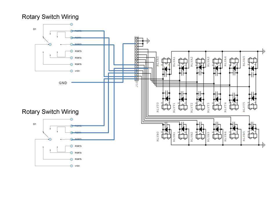
A dead simple way to run your 2×6 or 2×8. Connect the PORT nodes directly to the control inputs on the relay board. In this case if you choose the same antenna port for both radios, then radio A will get the antenna.
NOTE: If you acquired a switch from another ham please check to make sure it is not an early version of the 2×6 relay board from 2005. You cannot use this method on the original board design from 2005. Please reach out to me if you have a question about this.
Would you like a 2×12 switch??
You can use the ideas below to configure the 2×6 as a pair to be used as a 2×12 switch! Yes this can work. You are on your own to come up with a enclosure and how to physically support the boards. Go for it!!
