Home / Shop
Dual Band-Decoder/Controller Board
0 Reviews
$15.00
A one-time price of $15.00 will be added to your order.
2 Left in Stock
Manufacturer: KK1L Contest Gear

- Description
- Specifications
- Customer Reviews (0)
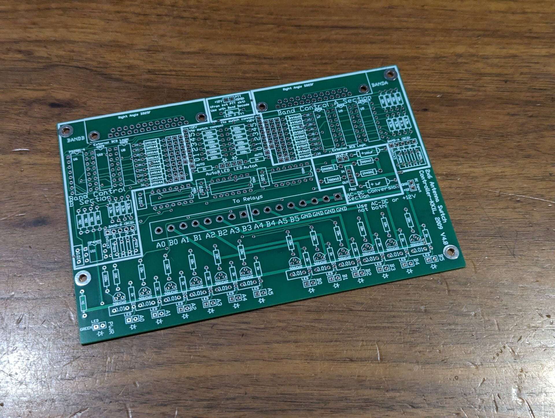
Dual Band-Decoder / Controller Board
The board includes two band decoders using 4 bit BCD from your radio or logging program. The board can be power directly with 12V DC or 18V P-P AC fed to the rectifier section. I laid the board out such that you can just add the components for the simple version of the controller, if you don’t need the band decoders for example. The band decode segment includes an option to lockout antenna switching while transmitting. If you do not need the PTT controlled lockout you can leave that segment out as well. These sections are clearly marked on the PC board and in the assembly documentation.
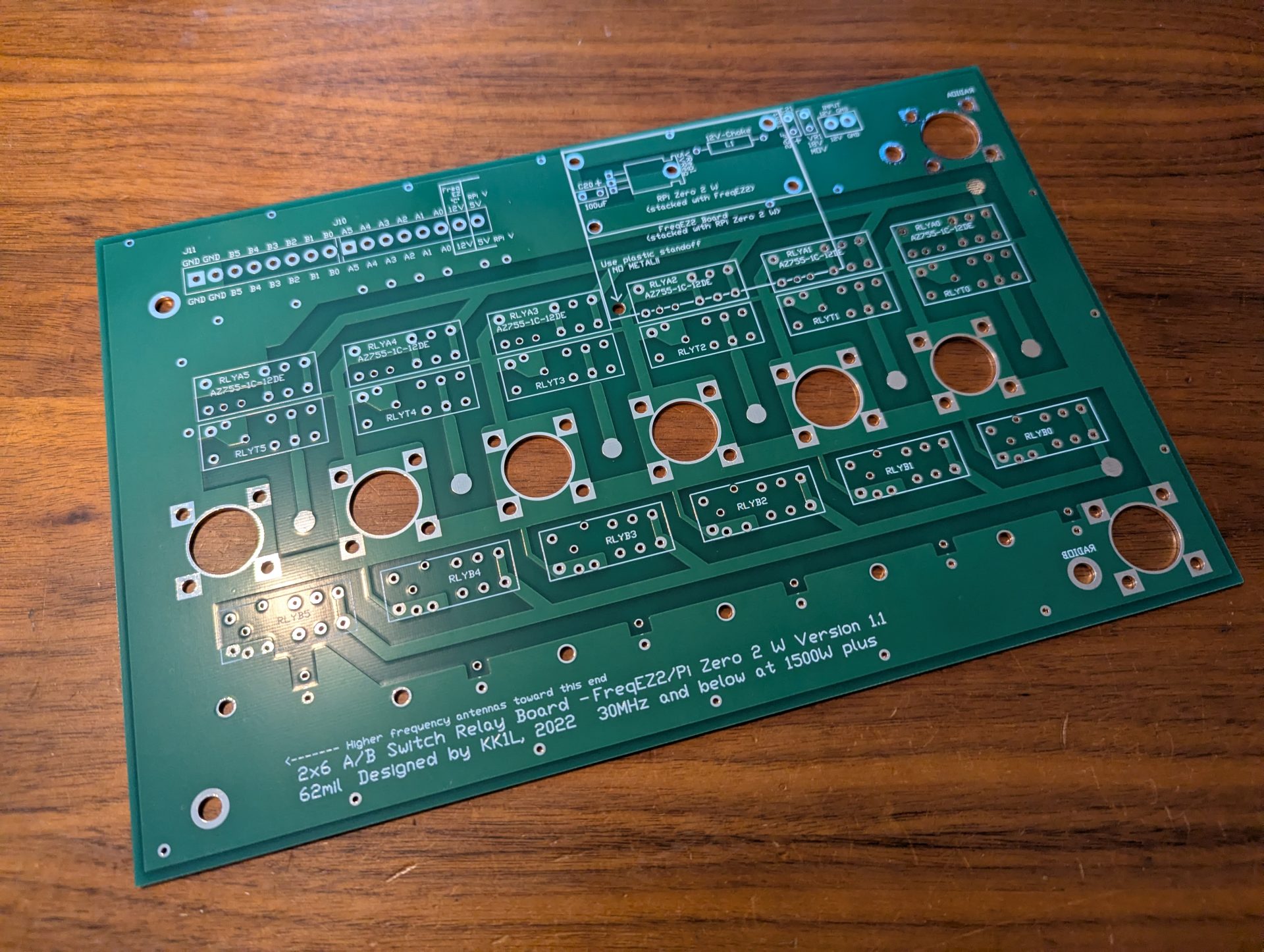
- Supports only 2×6 antenna switch board
- The board is laid out modularly as several independent circuits on the same board which are easily integrated
- One basic 2×6 antenna switch controller where active high Rotary A/B as inputs drive active high relay connections as outputs
- Two band decoders where active high BAND-A/B BCD inputs drive active high J15/J16 band decode outputs
- By connecting the band decode outputs to the rotary inputs you create a computer controlled 2×6 switch
- Optically isolated PTT lockout
- AC to DC converter section
- Protection for hot switching when using the BCD inputs.
- When PTT is GND the current antenna selections will be held until PTT is deasserted
- There is no hot switch protection for the manual active high switch inputs
- Only one radio can use an antenna port at a time
- No stealing! The first radio keeps the antenna until released
- LED indicates when antenna(s) is selected for each radio
- BCD band decoder support
- Opto-isolator inputs for each radio port using the “standard” W9XT, NA, TRLog format
- To wire the six contest band just short across from J15/J16 to the corresponding switch
- Only one radio port selectable per antenna. The first one to have the antenna keeps it until released.
- Can use rotary, toggle, or latched push button switches. Latched push button or toggle allow for multiple antennas per radio port (for stacking).
- The inputs are +12V active high logic and float when not selected.
- You might consider a 7 position rotary switch if also using the BCD inputs. This will allow for a “no select” position for the rig or computer to control the selections.
- Along with manual switching you can use BCD band data from your radio or logging program. The decoding follows the “standard” of NA, TRLog, and others.
- To wire the six contest band just short across from J15/J16 to the corresponding switch connections.
- You can also “wire OR” bands to one port.
- For example to put a tri-bander on Port5 you can connect the 10, 15, and 20m decoded outputs to the port 5 switch position.
- The inputs are optically isolated and convert from 5V or 12V active high logic to relay (12V) levels.
- CMOS devices (4028, 4011) take +12V VCC directly.
- Quad optoisolators convert external 5V/12V interface to +12V.
- Dimensions: 6.125″ x 4.0″
- High quality FR4 double sided, masked, and silk screened both sides
- Logical lock-out prevents a radio from “stealing” an antenna already in use
- BCD Band Decoder support
- Designed in sections, so you can build only what you need
- AC to DC regulator section (use if not providing +12V)
- Radio band decoder section for auto switching
- Basic switch input and relay control section
- Discrete pin in hole component design
- Supports 2×6 board only
There are no reviews yet, submit yours in the box provided.
Please sign in or create an account to submit a review for this product.