The relay board is designed to accept twelve active high (+12V) inputs to select the twelve antenna switching relays. I send +12V to each relay rather than ground each one to make it easier to shield the board. It is impossible to have both radios selecting the same antenna. External logic, if you choose to use it, can enforce “first come, first served”, or “no stealing” rules. I provide the option to have unused antennas either open, shorted to ground, or terminated to 50 Ohms. Terminating to 50 Ohms will minimize reflections on the feed lines on unselected ports keeps the interaction from those antennas at a minimum in the switch. It is also sufficient to remove static build up.
2oz copper is used on the PCB which can allow 2800W key-down into 50 Ohms the trace heating will be limited to an acceptable 10°C. This also supports 1500W+ at below VSWR of 3. Trace spacing prevents high voltage arc-over as well.
I have designed the switches with high RF integrity in mind to provide a hard to find DIY component for you to design around. Roll your own Raspberry Pi or Microcontroller based decoder and controller, or use the options I provide.
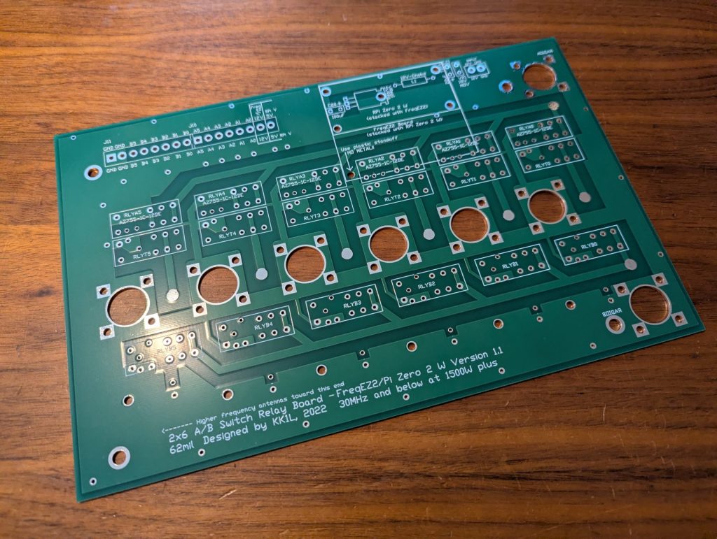
Construction Details
Illustrated assembly details and parts list
Mouser Parts List
Link to Mouser.com with a full parts list to edit and load in a cart!
Schematic Diagram
Circuit details
Performance Analysis
Jeff’s, AC0C, independent analysis of the 2×6 switch
Please note: All electronic parts are included in the project file. Any unneeded part can easily be removed from the Mouser order. There are “optional” parts included in the list PLEASE PAY ATTENTION FOR THESE. If you have questions please reach out to me.
Looking for more info or ideas…
Check out the FAQ link in the header or the twisties below
2×6 Assembly Parts List
These parts are available in the Mouser Project File link, and are easily available to edit and put into your Mouser shopping cart. I have no affiliation with Mouser, but just that it is super easy and convenient. Get the parts however you would like!
Some stuff from Amazon you could consider for the build https://www.amazon.com/hz/wishlist/ls/XDS80BGQWSBG?ref_=wl_share
Basic Build Parts:
- 12 – Diodes 1N4001 (relay back EMF suppression)
- 12 – 0.01uF ceramic capacitor (relay noise suppression)
- 6 – 50 Ω 50W Thick Film TO-220-2 (or 51Ω 3W Metal Oxide Resistor)
- 18 – RZH3-1C4-12 Relay or equivalent (Form-C SPDT non-latching 12V 16A 5mm pin pitch)
- 8 – SO-239 Launcher (chassis mount)
- 2 – Euro 10 port Fixed Terminal Block (optional, but convenient)
- 16 – 6-32 x 1” stainless screws (length is generous)
- 32 – 6-32 stainless nuts
- 1 – 2×6: 7”x11”x 2” Hammond Al Chassis and bottom plate
Raspberry Pi Zero / FreqEZ Parts:
- 1 – Raspberry Pi Zero 2 W or Zero W (any RPi works, but small form factor is important for this install)
- 1 – UFL SMD connector (if not already on the R Pi Zero and you will add an external antenna)
- 1 – UFL to SMA chassis mount cable (if you will add an external antenna)
- 1 – FreqEz2 Band Decoder / switch control
- 1 – 100uH choke (optional…can substitute with a jumper/short)
- 1 – 5V 1A voltage regulator TO-220
- 1 – 100uF 16VDC electrolytic capacitor
- 1 – 22uF 35VDC tantalum capacitor
- 1 – 14V MOV
- 1 – Euro 2 port Fixed Terminal Block (optional, but convenient)
- 10 – M3 hex 10.0mm nylon threaded standoff (M2.5 fits better, but not available at Mouser)
- 5 – M3 hex 15.0mm nylon threaded standoff (M2.5 fits better, but not available at Mouser)
- 6 – M3 hex nylon nut (M2.5 fits better, but not available at Mouser)
2×6 Chassis Dimension Files (including Excellon drill file)
Switching using Cave Man Technology a.k.a. A rotary switch
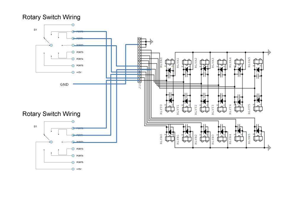
A dead simple way to run your 2×6 or 2×8. Connect the PORT nodes directly to the control inputs on the relay board. In this case if you choose the same antenna port for both radios, then radio A will get the antenna.
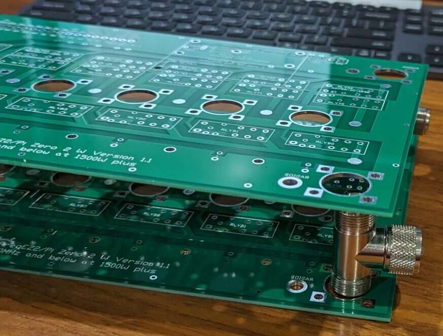
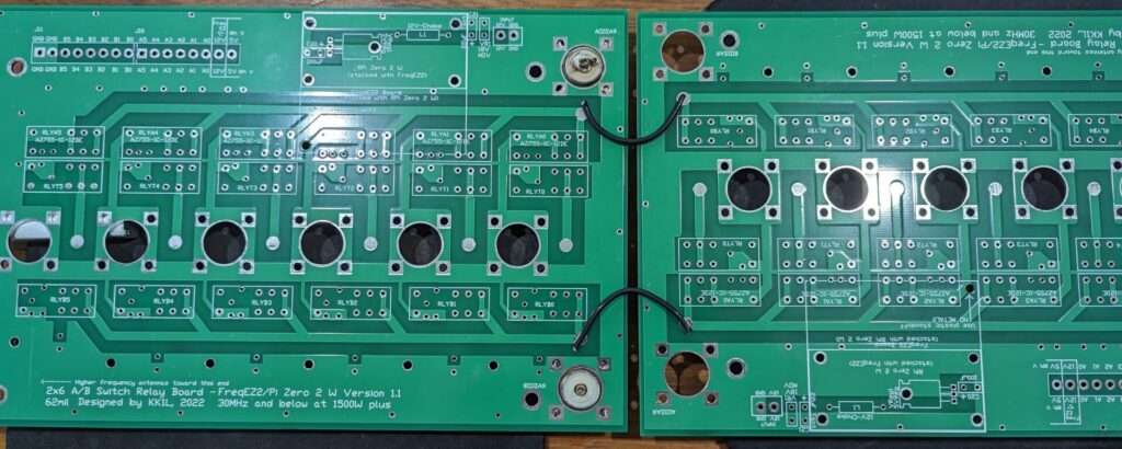
Would you like a 2×12 switch??
You can use the ideas below to configure the 2×6 as a pair to be used as a 2×12 switch! Yes this can work. You are on your own to come up with a enclosure and how to physically support the boards. Go for it!!