“Going Old School”
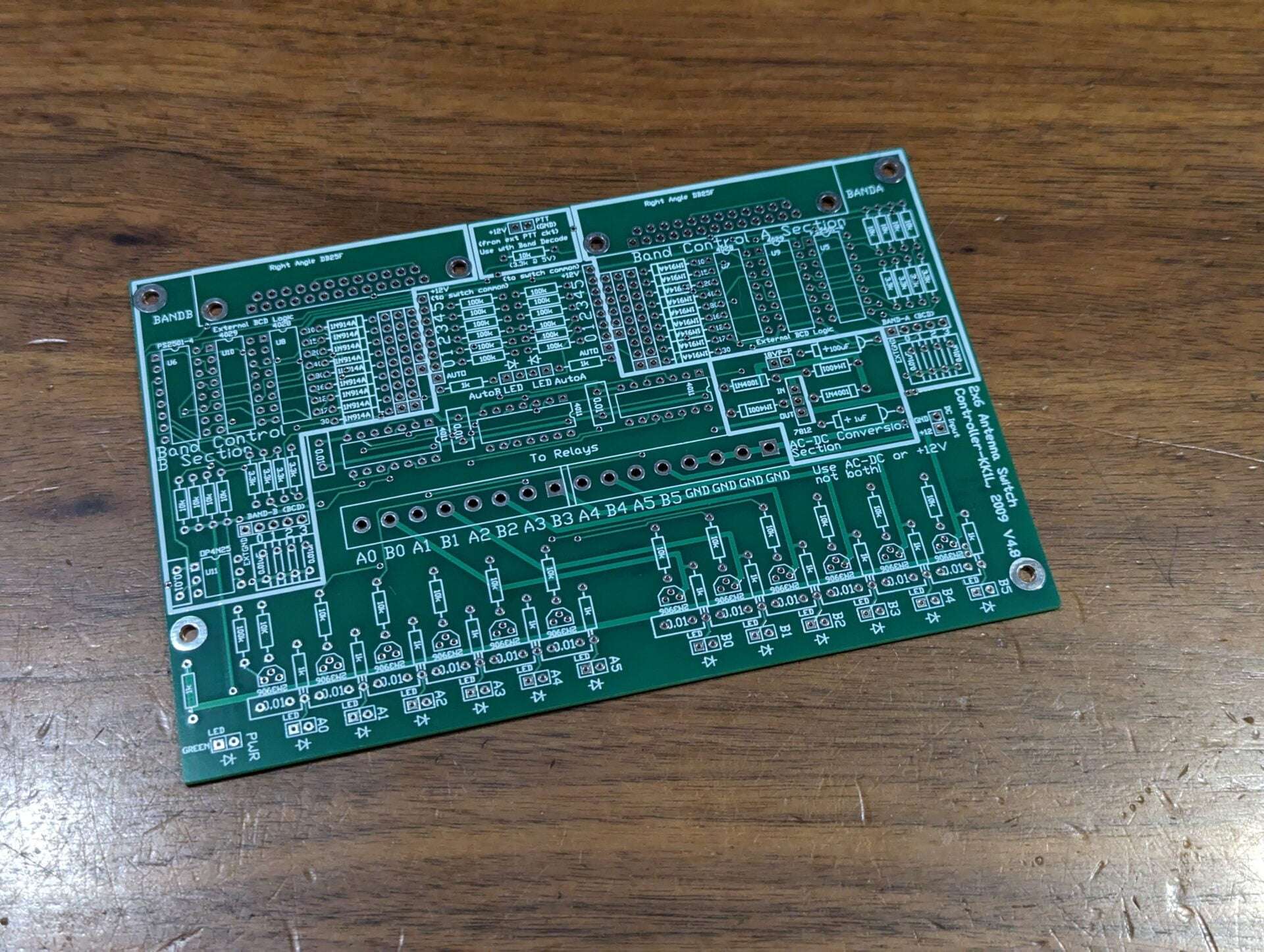
- Dimensions: 6.125″ x 4.0″
- Discrete pin in hole component design – you might have many of the components in your junk box!
- The board is laid out modularly as several independent circuits on the same board which are easily integrated
- One basic 2×6 antenna switch controller where active high Rotary A/B as inputs drive active high relay connections as outputs
- Two band decoders where active high BAND-A/B BCD inputs drive active high J15/J16 band decode outputs
- By connecting the band decode outputs to the rotary inputs you create a computer controlled 2×6 switch
- Optically isolated PTT lockout
- AC to DC converter section
- Protection for hot switching when using the BCD inputs.
- When PTT is GND the current antenna selections will be held until PTT is deasserted
- There is no hot switch protection for the manual active high switch inputs
- Only one radio can use an antenna port at a time
- No stealing! The first radio keeps the antenna until released
- LED indicates when antenna(s) is selected for each radio
- BCD band decoder support
- Opto-isolator inputs for each radio port using the “standard” W9XT, NA, TRLog format
- To wire the six contest band just short across from J15/J16 to the corresponding switch
- Only one radio port selectable per antenna. The first one to have the antenna keeps it until released.
- Can use rotary, toggle, or latched push button switches. Latched push button or toggle allow for multiple antennas per radio port (for stacking).
- The inputs are +12V active high logic and float when not selected.
- You might consider a 7 position rotary switch if also using the BCD inputs. This will allow for a “no select” position for the rig or computer to control the selections.
- Along with manual switching you can use BCD band data from your radio or logging program. The decoding follows the “standard” of NA, TRLog, and others.
- To wire the six contest band just short across from J15/J16 to the corresponding switch connections.
- You can also “wire OR” bands to one port.
- For example to put a tri-bander on Port5 you can connect the 10, 15, and 20m decoded outputs to the port 5 switch position.
- The inputs are optically isolated and convert from 5V or 12V active high logic to relay (12V) levels.
- CMOS devices (4028, 4011) take +12V VCC directly.
- Quad optoisolators convert external 5V/12V interface to +12V.
Construction Details
Illustrated assembly details and parts list
Mouser Parts List
Brings you to Mouser.com with a full parts list to edit
Schematic Diagram
Circuit details
Chassis Dimensional Drawing
Drill and punch dimensions for reference
Looking for more info or ideas…
Check out the FAQ link in the header or the twisties below
Dual Band Decoder / Controller Parts List
These parts are available in the Mouser Project File link, and are easily available to edit and put into your Mouser shopping cart. I have no affiliation with Mouser, but just that it is super easy and convenient. Get the parts however you would like!
Some stuff from Amazon you could consider for the build https://www.amazon.com/hz/wishlist/ls/XDS80BGQWSBG?ref_=wl_share
Relay Control Section – This is all you need to build if you are going fully manual:
- 3 – CD4011 (sockets optional)
- 2 – Euro Connector (optional, but convenient)
- 12 – PNP Transistor MPSA92 (nearly any PNP will work. Location marked “2N3906”)
- 13 – 100K Ohm 1/4W (not critical…47K to 150K is fine)
- 12 – 5.6K Ohm 1/4W (board is marked 10K)
- 15 – 1K Ohm 1/4W (can change to vary LED brightness)
- 3 – 0.01uF ceramic (not critical!! 0.1uf & 0.001uF are okay too)
- 12 – 27V MOV (near transistors marked “0.01”)
- 2 – 7 Position Rotary Switch
- 1 – 72 pin 100mil SIP Header (optional)
- 1 – Green LED (power)
- 12 – Red LED
- 13 – LED Chassis Clip (drill 11/64”)
Band Decode Sections – These can be used separate from the relay control section if desired:
- 1 – 4N25 1 Ch Opto-isolator
- 2 – PS2501-4 4 Ch Opto-isolator
Note: Can use PS2505-4 which can allow active or active 0 BCD inputs - 2 – CD4028
- 2 – CD4029
- 18 – Switching Diode 1N914 (most any switching diode will do)
- 8 – 3.3K Ohm 1/4W
- 9 – 10K Ohm 1/4W
- 9 – 0.01uF ceramic (not critical!! 0.1uf & 0.001 uF are okay too)
- 2 – DB25 PCB Mount Female
- 2 – Yellow LED (optional for Auto mode)
- 2 – 1K Ohm ¼ W (optional for Auto mode)
- 2 – LED Chassis Clip (drill 11/64”)
AC-DC Converter Section:
- 1 – 12V Regulator
- 4 – Rectifier 1N4001
- 1 – 100uF 50V
- 1 – 1uF 50V
- 1 – SPST Switch