Home / Shop
Dual Band-Decoder/Controller Board

- Description
- Specifications
- Customer Reviews (0)
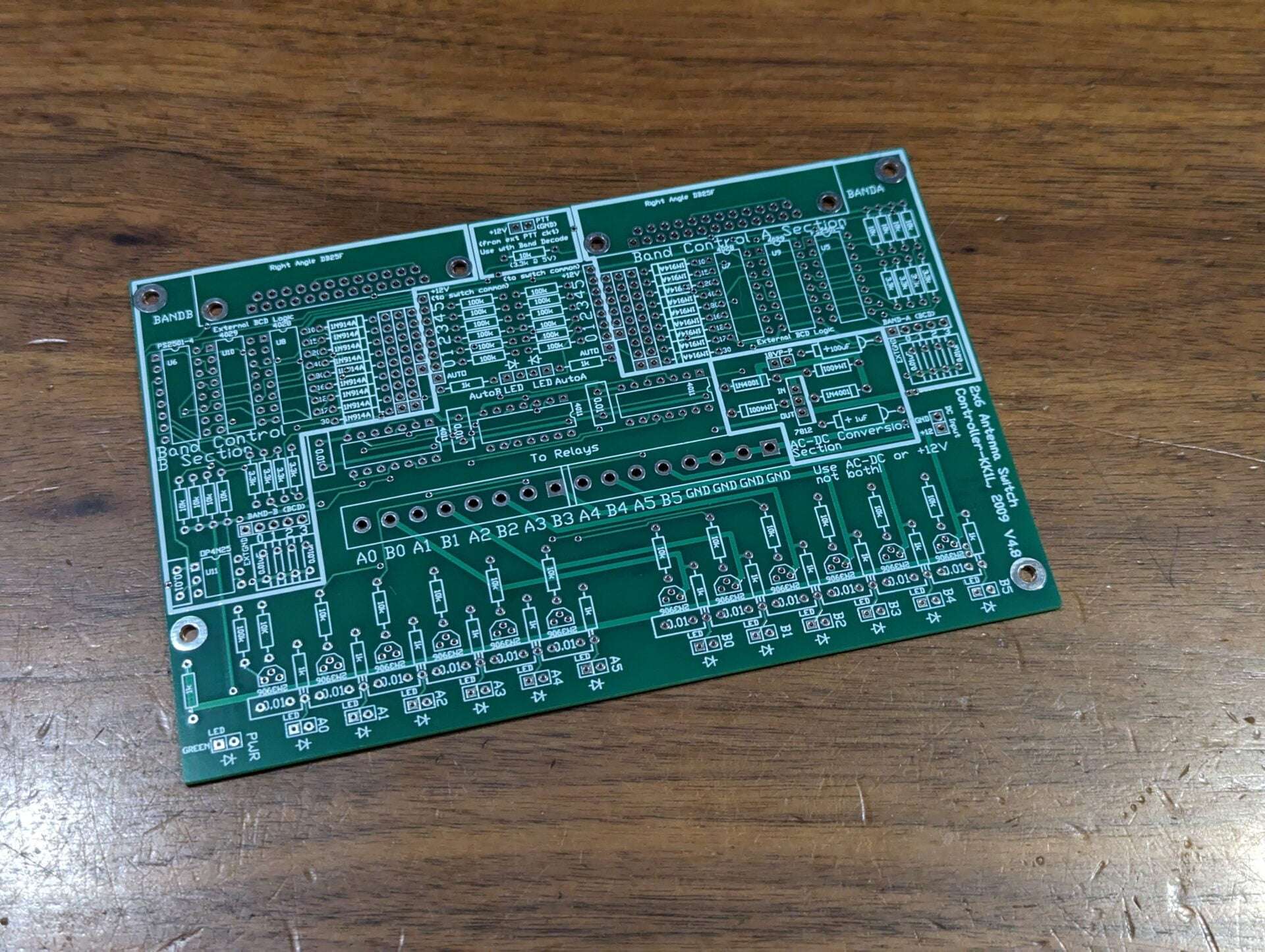
Dual Band-Decoder / Controller Board
The board includes two band decoders using 4 bit BCD from your radio or logging program. The board can be power directly with 12V DC or 18V P-P AC fed to the rectifier section. I laid the board out such that you can just add the components for the simple version of the controller, if you don’t need the band decoders for example. The band decode segment includes an option to lockout antenna switching while transmitting. If you do not need the PTT controlled lockout you can leave that segment out as well. These sections are clearly marked on the PC board and in the assembly documentation.
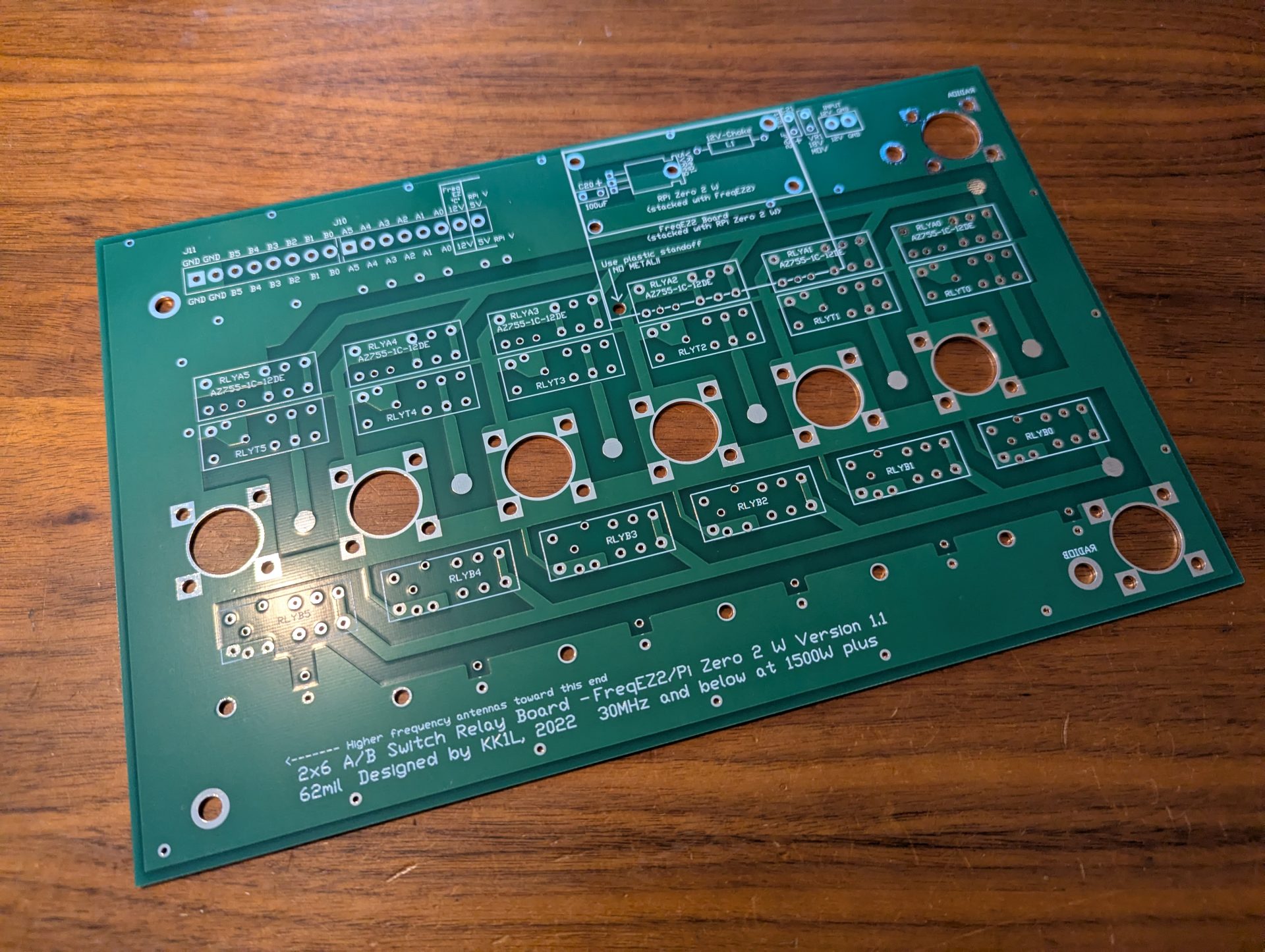
- Supports only 2×6 antenna switch board
- The board is laid out modularly as several independent circuits on the same board which are easily integrated
- One basic 2×6 antenna switch controller where active high Rotary A/B as inputs drive active high relay connections as outputs
- Two band decoders where active high BAND-A/B BCD inputs drive active high J15/J16 band decode outputs
- By connecting the band decode outputs to the rotary inputs you create a computer controlled 2×6 switch
- Optically isolated PTT lockout
- AC to DC converter section
- Protection for hot switching when using the BCD inputs.
- When PTT is GND the current antenna selections will be held until PTT is deasserted
- There is no hot switch protection for the manual active high switch inputs
- Only one radio can use an antenna port at a time
- No stealing! The first radio keeps the antenna until released
- LED indicates when antenna(s) is selected for each radio
- BCD band decoder support
- Opto-isolator inputs for each radio port using the “standard” W9XT, NA, TRLog format
- To wire the six contest band just short across from J15/J16 to the corresponding switch
- Only one radio port selectable per antenna. The first one to have the antenna keeps it until released.
- Can use rotary, toggle, or latched push button switches. Latched push button or toggle allow for multiple antennas per radio port (for stacking).
- The inputs are +12V active high logic and float when not selected.
- You might consider a 7 position rotary switch if also using the BCD inputs. This will allow for a “no select” position for the rig or computer to control the selections.
- Along with manual switching you can use BCD band data from your radio or logging program. The decoding follows the “standard” of NA, TRLog, and others.
- To wire the six contest band just short across from J15/J16 to the corresponding switch connections.
- You can also “wire OR” bands to one port.
- For example to put a tri-bander on Port5 you can connect the 10, 15, and 20m decoded outputs to the port 5 switch position.
- The inputs are optically isolated and convert from 5V or 12V active high logic to relay (12V) levels.
- CMOS devices (4028, 4011) take +12V VCC directly.
- Quad optoisolators convert external 5V/12V interface to +12V.
- Dimensions: 6.125″ x 4.0″
- High quality FR4 double sided, masked, and silk screened both sides
- Logical lock-out prevents a radio from “stealing” an antenna already in use
- BCD Band Decoder support
- Designed in sections, so you can build only what you need
- AC to DC regulator section (use if not providing +12V)
- Radio band decoder section for auto switching
- Basic switch input and relay control section
- Discrete pin in hole component design
- Supports 2×6 board only
Related Products
As a reminder you will need other components to complete your project. Below are some links to help you. I do my best to get your order to you quickly and update the site of any persistent delay (on vacation or business travel for example). I will respond to your order email with any issues. Don’t hesitate to reach out with questions Contact Me.
Copyright
This software is copyrighted freeware. You can use, modify, and distribute the software provided that you offer it and any derivative works as freeware. Any commercial use must be approved in writing by the author.
Disclaimer
This software controls equipment that could be damaged by said software. You are responsible for installing, configuring, testing and ensuring that the software performs properly in your environment. The author cannot be held liable for any direct, indirect, consequential or incidental damages to other pieces of software, equipment, goods or persons arising from the use of this software. By downloading this software you accept the above terms of copyright and disclaimer.
FreqEZ v2.2.0 Windows Console – software to be installed on each computer accessing the FreqEZ
Standard Windows setup program:
Download and unzip this ZIP archive. Then run the setup executable:
FreqEZ Windows Console: FreqEZ WinConsole_v2.2.0.zip
FreqEZ v2.2.0 Raspberry Pi Controller – software to be installed on the Raspberry Pi connected to the FreqEZ
Burn microSD Disk Method (RECOMMENDED):
- Raspberry Pi Imager – for creating the Raspbian operating system image to the microSD card. Follow instructions below
- Launch Raspberry Pi Imager
- Click the APP OPTIONS button at bottom of the window (the white button with the red outline)
- Under Content Repository choose Use custom URL
- enter: https://freqez.kk1l.com/imager.json
- press APPLY & RESTART
- Choose the Device Setup step (should be already selected on left)
- Scroll to the very bottom and double-click No filtering
(or select and press NEXT)
- Scroll to the very bottom and double-click No filtering
- Double-click FreqEZ Trixie Headless or Desktop at the top of the list
(or select and press NEXT) - Choose the storage device (microSD) to write
- For Customisation steps enter a hostname, locale, username, password, WiFi SSID, passphrase
- hostname of ezcontroller-1 is not a bad choice
- Leave “Capital city” as is…it does not matter
- username = ez, password=freqez is not a bad choice. Don’t choose “pi”
- ENABLE SSH!
- Proceed to write the image to your SD card
- The IMG file will be automatically downloaded and burnt to the micro SD card
Manual File Copy Method (ALTERNATE for “experts”):
- The files in this FreqEZ RPi Controller ZIP archive can be downloaded and manually copied to specific locations within the Raspberry Pi file structure.
- Step-by-step instructions can be found in the “APPENDIX: Alternative Method for Preparing the microSD Card” section of the documentation by clicking on Help in the v2.2.0 Windows Console or opening the on-line Help file FreqEZhelp.pdf.
- FreqEZ Raspberry Pi Controller FOR BULLSEYE or earlier!!: FreqEZ_RPiController_v2.2.0.zip
- FreqEZ Raspberry Pi Controller FOR BOOKWORM or later!!: FreqEZ_RPiController_v2.3.0.zip
- Note there is a “freqezrpi” executable for either 32 bit or 64 bit. You must choose the correct version.
FreqEZ v2.2.0 Help PDF file
FreqEZ Documentation / Help file: FreqEZhelp.pdf