Discontinued
Contact me if you are interested
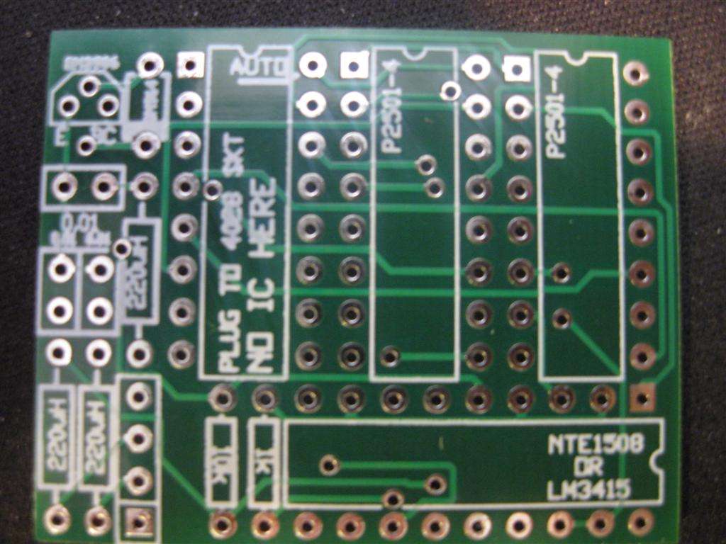
- Dimensions: 1.8″ x 1.3″
- NTE1508 Dot/Bar Driver is difficult to find – required part
- High quality FR4 double sided 1oz copper, masked, and silk screened both sides.
- A fully opto-isolated interface between an Icom radios analog voltage band data output and the Antenna Switch Controller
- Designed as a “daughter card” which plugs into the CD4028 socket of one or the other port of the controller
- Takes the place of all the components of one of the two decoders
- Can be used as a stand-alone decoder as well!
- Discrete pin in hole component design – you might have many of the components in your junk box!
Construction Details
Illustrated assembly details and parts list
Mouser Parts List
Brings you to Mouser.com with a full parts list to edit
Schematic Diagram
Circuit details
Looking for more info or ideas…
Check out the FAQ link in the header or the twisties below
Icom Decoder Daughter Card Parts List
These parts are available in the Mouser Project File link, and are easily available to edit and put into your Mouser shopping cart. I have no affiliation with Mouser, but just that it is super easy and convenient. Get the parts however you would like!
Relay Control Section – This is all you need to build if you are going fully manual:
- 1 – Diode 1N4148
- 3 – 0.01uF ceramic capacitor
- 3 – 220uH radial inductor
- 2 – 1kΩ 1/8W 1% Resistor
- 1 – 8.2kΩ 1/8W 1% Resistor
- 1 – 10kΩ 1/8W Resistor
- 1 – LM3415 or NTE1508 Dot/Bar Driver DIFFICULT TO FIND
- 1 – 2N3906 PNP transistor
- 2 – PS2501-4 4Ch opto-isolator
(if you already build the decoder on the controller board you don’t need these) - 3 – 16pin DIP socket
- 1 – 18pin DIP socket
- 2 – 9 position header 100mil pitch
- 1 – each optional pad resistors 604Ω, 806Ω, 1.2kΩ, 1.4kΩ